SPI (Serial Peripheral Interface Bus)
o Summary
모토로라의 de facto standard에서 만든 전이중 Full-Duplex 동기식 직렬 연결이다. Master-Slave 방식이며, SS(Slave Select)를 이용하여 개별 Slave와 연결됨.
o Operation
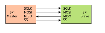
- The SPI bus specifies four logic signals:
. SCLK: serial clock (output from master);
. MOSI: master output, slave input (output from master);
. MISO: master input, slave output (output from slave);
. SS: slave select (active low, output from master).
- Alternative naming conventions are also widely used:
. SCLK: SCK, CLK: serial clock (output from master)
. MOSI: SIMO, SDO, DO, DOUT, SO, MTSR: serial data out; data out, serial out, master transmit slave receive
. MISO: SOMI, SDI, DI, DIN, SI, MRST: serial data in; data in, serial in, master receive slave transmit
. SS: nCS, CS, CSB, CSN, nSS, STE: chip select, slave transmit enable (active low, output from master)
The SDI/SDO (DI/DO, SI/SO) convention requires that SDO on the master be connected to SDI on the slave, and vice versa. Chip select polarity is rarely active high, although some notations (such as SS or CS instead of nSS or nCS) suggest otherwise.
o 장단점
- 장점
. Full duplex communication
. Higher throughput than I²C or SMBus
. Complete protocol flexibility for the bits transferred
Not limited to 8-bit words
Arbitrary choice of message size, content, and purpose
. Extremely simple hardware interfacing
Typically lower power requirements than I²C or SMBus due to less circuitry (including pull up resistors)
No arbitration or associated failure modes
Slaves use the master's clock, and don't need precision oscillators
Slaves don't need a unique address ? unlike I²C or GPIB or SCSI
Transceivers are not needed
. Uses only four pins on IC packages, and wires in board layouts or connectors, much fewer than parallel interfaces
. At most one unique bus signal per device (chip select); all others are shared
. Signals are unidirectional allowing for easy Galvanic isolation
. Not limited to any maximum clock speed, enabling potentially high throughput
- 단점
. Requires more pins on IC packages than I²C, even in the three-wire variant
. No in-band addressing; out-of-band chip select signals are required on shared buses
. No hardware flow control by the slave (but the master can delay the next clock edge to slow the transfer rate)
. No hardware slave acknowledgment (the master could be transmitting to nowhere and not knowing it)
Supports only one master device
. No error-checking protocol is defined
. Generally prone to noise spikes causing faulty communication
. Without a formal standard, validating conformance is not possible
. Only handles short distances compared to RS-232, RS-485, or CAN-bus
. Many existing variations, making it difficult to find development tools like host adapters that support those variations
. SPI does not support hot plugging (dynamically adding nodes).
o Revision
Master는 SS(Slave Select)를 통해 Slave를 정함
-> Master는 MOSI(Master Output Slave Input)으로 SCLK를 전송
-> Slave는 SS를 통해 수신모드로 들어가 MOSI를 통해 전달되는 신호를 SCLK에 맞춰 수신
-> 신호는 8 or 16-bits or 그 이상의 비트로 조합하여 전송
o Reference
- Kor Wiki : http://ko.wikipedia.org/wiki/%EC%A7%81%EB%A0%AC_%EC%A3%BC%EB%B3%80%EA%B8%B0%EA%B8%B0_%EC%9D%B8%ED%84%B0%ED%8E%98%EC%9D%B4%EC%8A%A4_%EB%B2%84%EC%8A%A4
- Eng Wiki : http://en.wikipedia.org/wiki/Serial_Peripheral_Interface_Bus
- http://blog.daum.net/trts1004/12108902